December 2, 2014

Raided In Volume!


Spify title, I know – but we’re not talking police raids by the dozens here. I’m discussing how to get the most out of a RAID. Its an age old debate, should you go with a RAID1 or perhaps a RAID5 or RAID6? What are the benefits? Well all this depends on exactly what you’re trying to acheive with the RAID setup. The pertinent questions one has to answer is:

1) Do you want more space?
2) Do you want redundancy?
3) Do you want to protect your data from drive faulure?
4) Do you mind your write speeds not being as fast as they should be off a single drive?

Points (2) and (3) more or less tie into the same thing though the experienced crowd may be crying foul on point (3) “RAID is not a backup!”. And yes, it is NOT a backup, but it allows the less critical some sembelence of one.

To start the ball rolling, lets look at the RAID levels that are commonly in play.

RAID LEVEL DESCRIPTION BENEFITS DRAWBACKS
0 Stripping of data across multiple disks Good Performance No Redundancy
1 Duplicating data over equivalently sized disks Good read/write performance with redundancy Expensive – need twice the required space
5 Data written in blocks across all drives, single parity block Good read performance for small, random I/O requests, has redundancy Write performance and read performance for large, sequential I/O request is poor, failure of more than one disk simultaneously will render all data lost
6 Data written in blocks across all drives, dual parity block Good read performance for small, random I/O requests, has redundancy Write performance and read performance for large, sequential I/O request is poor, failure of more than two disks simultaneously will render all data lost

If you want more detailed info, check this link out.

Most home users would go for RAID 0, RAID1 or combo RAID10. RAID0 maximizes the capacity so thats an obvious reason, but why choose RAID1, even though it reduces your capacity by 50% immediately? Well lets face it, as home users, one wouldn’t spend a bomb on a Synology or QNAP 4 to 8 bay RAID enclosure that costs easily over $1000 without any disks (or even $600 for a WD EX4 4 bay system). No, home users would simply get a 2 bay model which conveniently brings your choices down to only RAID0 or RAID1. If you’re a capacity freak, you’ll want all your disks striped together and if you are worried about backups, then sacrificing 50% of the total capacity isn’t anything you’d be worried about. The folks with more money to burn would get a 4 bay system and stripe 2 disks together to get a larger space then mirror it to another 2 disks, forming your RAID 10.

For a more professional setup, we consider capacity, redundancy, data protection and write access. Yeah, thats basically all 4 points. There is simply no compromise for critical corporate data. We need to maximize space so more data can be stored, create redundancy so that data is always available, make sure data can be rebuilt should drives fail as well ensure that access to the system is fast enough not to cause delays and finally have a constantly updated copy of the data that can be copied from if the main data is corrupted. That last point is the REAL backup. For all those points, these are the instances we employ RAID5 or RAID6 with a combination of RAID1 or RAID0, to give RAID50, RAID51, RAID60 and RAID61. On top of these we employ fast cache (which is usually an array of SSD disks to take data in quickly and hold it while its written to the actual RAID setup) and then a full back up solution like de-dup which is offered by a number of vendors. Yes, gone are the days when we use a super slow DDS2/3/4 tape library to do backups – seriously you want to spend 96 hours backing up 60TB of data when you can churn out 200TB of data under 24? Not to mention how long it will take to restore that data.

Maximizing the points is something that has to be done carefully. You don’t want to maximize capacity and realize that you don’t have enough data protection or redundancy, or vice versa. Never mind the unrecoverable errors (URE) for RAID5 and RAID6 setups (mostly rubbish by the way – mostly) and problems with larger disks in the calculations required to read and write your data. With so many considerations, it makes one wonder why we even consider anything other than a RAID10. Well cost is a major factor – fortunately cheap storage pods, like BackBlaze are all the rage these days. JBOD (Just a Bunch Of Disks) enclosures which can interconnect to each other, forming an ever growing storage. Now just because they are cheap doesn’t mean you’re going to go all crazy and start getting a bunch of these for RAID10. Be smart and look at how to avoid the headache of RAID management particular to your own requirements. There is no way to tell you how to do this, its just something you have to figure out, but I can go with an example.

We needed a large storage capacity, a datastore of sorts, something in the region of over 80TB (for a start) with the ability to grow as and when necessary without affecting current data. The data being written to it had to have very strong redundancy (research data that has to be kept for a minimum of 7 years), speeds of read and write were irrelevant. We opted for 80 x 4TB disks giving us a raw capacity of 320TB. Now with best practices we could have had 10 x 8 drive hardware RAID6 forming 10 logical disks (most straight forward) in a single logical volume which would be ~200TB after formatting, but that would have seriously screwed us over if any two disks failed in a RAID set simultaneously – don’t say it doesn’t happen, it does and it has!We could have gone with 5 x 8 drive software RAID6 forming 5 logical disks with a hardware RAID1 on the whole thing, forming 1 logical volumes, which would have given us better protection but still iffy and would reduced our capacity to roughly ~100TB after formatting, but would have impeded our ability to grow the capacity easily given that the RAID1 would require logical disks of equal size. What we eventually ended up with was a 6 x hardware RAID6 with 12 disks, each disk on a software RAID1, forming 6 logical disks within a single logical volume with 8 global hot spares. A hardware RAID forming logical disks, with a software RAID for each physical disk, all in a logical volume (hence the title). Nothing straight forward about this solution, let me tell you that much, but it will save a whole lot of time and trouble compared the others.

raid51LVM

As far as protection goes, its doesn’t get better than this and it also allows for more logical disks to be added without considering the need to have equivalent disk capacities as the other logical disks. So long as the disks within the logical disk forming the software RAID1 were of equivalent size, it didn’t matter much. What was the trade off of this super-protected-easy-to-grow setup? Space. Pure and simple. By utilizing this setup, we had 6 x RAID6 (2 x parity) mirrored which worked out to be only 16TB x 6 or ~90TB after formatting. Did it serve our purposes? More than 80TB? Check. Able to grow easily without affecting current data? Check. Strong redundancy? Check.

In fact the other possibilities would also have given us a reasonable solution, but issue is in the management of the solution, especially when failure occurs. Most folks, I find, don’t seem to take what needs to be done in failure situations into consideration. They only look at the working scenario and say  “we have redundancy, so we’re ok”. They don’t consider how long it takes to rebuild, what are their contingencies during rebuild so that data is still accessible, do you have to port data out before adding more disks, etc. For us, we don’t like to take chances with research data, so even with this super-protected system, we still have a smaller system that we sync data from this 90TB datastore to. The size of the actual writable data is only about 30TB at the moment, so a smaller (60TB), less protected system (RAID51) holding an exact copy will give us a fail over option if we need to work on the actual datastore and the users won’t even know the main datastore is down.

Main point – know what you need and don’t always take the most straight forward solution. It might not seem like its worth the trouble, because things are always smooth when systems work, but its what happens when they don’t and what you have put in place to mitigate those scenarios, that separates the real techs from the wannabes. Which are you?

UPDATE:

Some folks have been telling me my diagram is wrong and that the parity shouldn’t be on individual disks. Yes, that is right, they shouldn’t. In modern systems the parity is distributed along all the disks, but I was using single disks in presenting the parity data so that it was immediately apparent how much usable disk space was available. Think of the diagram as a logical, not physical representation.

November 30, 2014

OSMO


OSMO-01

If you’re an iPad user with young kids and you haven’t heard about OSMO yet, which planet have you been on?

Making use of a unique periscope like mirror system attached over the front camera of your iPad (2 and above, Minis included), it allows for interaction with the application by doing things (arranging shapes, writing, drawing, etc) at the area just infront of the iPad’s screen. Designed primarily for kids, the technology uses the front camera to scan objects, shapes and even well defined drawn outlines in real time back into the application which can then alter the way the application runs.

OSMO-02
The Newton game for exaple, requires kids to get balls dropping from the top of the screen to hit a particular target. The kids can put objects or draw lines in the space infront of the iPad (on a piece of paper of course!) and the line or object will be scanned (very roughly) into the game and the balls will bounce, or roll off the shape.

There is also Tangram, which challenges the player to form predefined designs using solid colored shapes (part of the set). Words is a fun way for kids to learn spelling by forming the words using square pieces with letters (also part of the set) depicting the picture shown on the iPad. You can even upload your own pictures and create your own game for your kids.

OSMO-04
I got a set for Hayden during their launch period for about S$80 and its been a hit – he loves Newton and Tangram and I think he is almost done with all the Tangram designs. The system is safe and easy enough for him to setup on his own without an adult present too.

If you’ve got young kids, check the website out and get one, your kids will love it and folks won’t be bugging you about kids with iPads not learning anything useful!

UPDATE:

OSMO have just released a new app called ‘Masterpiece’ – a drawing application using the OSMO system thats pretty fun! Check it out here.

November 2, 2014

Layer X Devices


We’re talking networking layers folks! The layers are the subdivisions of the Open Systems Interconnection (OSI) model which characterizes the functions of the communications flow between devices, as shown in the image below.osiSo why this particular topic? As I mentioned, I’ve been busy, mainly with an office and datacenter relocation and few consults for other departments, two of which were very network heavy. If theres one thing I noticed during the many meetings and discussions for these consults, was that a lot of folks (even those who are supposed to be network savvy) have a very unclear concept of the various “layers” that networking devices have. The other thing I noticed, is that those who are clear about them, can’t explain things simply enough for those who don’t understand them, so I want to try and clear things up. Now I don’t profess to be able to simplify things sufficiently either, but lets give it a shot.

Basically the layers in the image represent how, for example, this blog appears on your computer screen.

step 7 (webserver) –[data]– step 1 <—- cable —-> step 1 –[data]– step 7 (browser)

So you request for a html page by typing in a URL on your browser, the browser takes that URL, does its conversion of the host and domain name to an IP and packs the request into a TCP packet and sends it out through your LAN cable and the packet goes through your switch and then to the ISP’s router which tells it which path to take to reach the webserver of the URL you wanted and it reaches another router where the said webserver’s network is connected, gets told to go to a particular switch where the webserver is hooked up to and since it is HTML data you are requesting, it sends it by default to port 80 of the webserver. The webserver then takes the HTML page you wanted and coverts and compresses it into some format, then packs that into a TCP packet and passes that packet back down to the HTTPd port of the webserver, up the switch its hooked onto, back to the router who tells its which path to take to get back to your browser and it will travel to the router  of your home network and down to the switch where your pc (browser) is connected to and your browser will decompress and unconvert it and display it for you to see.

Man that was tiring and confusing. Go read the above paragraph five times, if you haven’t torn your hair off by then,  you probably understand what I’m talking about. Its just a flow, so unless you intend to take an exam on this, don’t worry too much about getting confused. In any case, I only want to discuss 2 particular layers. By the way, if you are intending to take an exam on this, then for goodness sakes, get off my blog and go read a real textbook!

We hardly talk about layer 1 devices in terms of the OSI layer and layer 4-7 devices are typically for select operations (L4 – typically load balancing, L5-6 TCP issues, L7 – application). What interest us IT architects and networking folks is layers 2 and 3 because these are key in how data gets moved about in a network and how to connect various networks together. For example, you can have switches (layer 2) connect your various devices together so they can talk to each other and transfer data to each other, that is considered a “single network” or a LAN. You could set up a few of these “single networks” each with their own switch (creating a few LANs), but how would you make them talk to each other? And thats what your router (layer 3) is for. Each of those “single networks” connected to a router would enable intercommunication between the “single networks”. Based on certain routing tables or other IP logic, data is passed from one network to another.

In a simplistic nutshell:

Layer 2 devices:
– connect machines together to form a LAN
– uses ARP to convert an IP address to a MAC address
– transports data to network port where a machine with the destination MAC address is

In a building-lift analogy, switches are liftshafts, floors of the building are the network ports (which have devices connected to them), passengers are the data. Passengers (data) can go from floor to floor (network ports where devices are connected) to access different units (devices) by traveling though the liftshaft (switch), as shown below.

 lift-switch-analogy-comparison

Layer 2 – Lift Analogy

Layer 3 devices:
– connect different networks (eg: LANs) together
– transports data from network to network, based on destination IP address

Sticking with the lift analogy, the building the lift shaft is in, is your LAN, skybridge(s) are your routers. Passengers (data) can go from floor to floor (network ports) to access units (devics) by travelling through the liftshaft (switch) and if they need to go to a unit (device) in another building (LAN), they will take the liftshaft (switch), head for the skybridge (router), go to the other building (LAN) and then take the liftshaft (switch) of that building (LAN) to get to the floor (network port) of that building (LAN) where the unit (device) is. Yeah I’d be confused too if I wasn’t the one explaining things – just look at the diagram for clarity. Its all pretty simple.

router-lift-skybridge-analogy-2

Layer 3 Skybridge Analogy

We then come to the “Layer 3 Switching Device”. This is all the rage now, as almost every SOHO (Small Office Home Office) “router” is a Layer 3 Switching Device. Why did I put the term ‘router’ in quotes? Because the terminology isn’t quite right. The similarities are there, as explained in the “About Tech” article:

“…a layer 3 switch is a high-performance device for network routing. Layer 3 switches actually differ very little from routers. A Layer 3 switch can support the same routing protocols as network routers do. Both inspect incoming packets and make dynamic routing decisions based on the source and destination addresses inside…”

however there is a clear difference. From the CiscoPress Book, “Cisco LAN Switching“, pages 451-453, authored by Kennedy Clark and Kevil Hamilton:

“…a Layer-3 switch (routing switch) is primarily a switch (a Layer-2 device) that has been enhanced or taught some routing (Layer 3) capabilities. A router is a Layer-3 device that simply does routing only…”

So “Layer 3 Switch” is essentially a marketing term, blurring the lines between the actual definition of layer 2 and layer 3 devices. Actual layer 3 devices make use of hardware, specifically “application-specific-integrated-circuits” or ASIC hardware to achieve its functionality, while the so called layer 3 switches use software to get things done.The useful thing about having software doing things, is that you can bundle other stuff with it, such as QoS, Firewalls and NAT.

So what was the problem with the vendors for our consults? They didn’t know difference between an L2, L3 and L3 switch. Our design called for an L3 switch with NAT, the vendors said they would give us the “Rolls Royce” of L3 switches, which would cover all the bells and whistles like NAT, VPN, vLANs and the like. End of the day, this “Rolls Royce” was nothing more than a “Camry” – an L2 switch with advanced monitoring and ACLs. Guess who had to start screaming at people?

Anyway, I hope the above has given some clarity (if not more confusion) to the difference between the L2, L3 and L3 switch situation – don’t get caught unaware if you’re doing a network design and most importantly, don’t get caught by me!

October 24, 2014

Office Move


This is what occupied the bulk of my time this year – about 5 months of it in fact, from late April till early October. Lots of things happened during that time and I was very quickly reminded of why I didn’t particularly enjoy Data Center (DC) design and construction projects. Its hard enough coming to an agreement with the contractors on the design, especially when we know what we want, whats available and what the vendor can do and the sub contractors are trying to find ways to do things easily and quickly and hence telling you everything you want “can’t be done” (good thing our main contractor was a solid chap who kept the sub contractors in line for the most part), but when you throw in the estate and facilities management teams who have no clue about DC design and construction and are trying to force every rule in the book down your throats, then its basically a nightmare. The number of people I had to tell off and put down in those 5 months, must have set some kind of record. I’ll spare you the details.

We designed the DC from scratch and thankfully the tender process selected a good vendor to deliver and they (eventually) did. The  DC has temperature control, water leak detection, FM200 fire suppression, proximity card and biometric access, SMS and email alert systems, a redundant auto cut in/out UPS with an hour long rundown time (an nearly 2 meter high cabinet full of batteries) and remote access/monitoring of almost everything. The DC can take up to twelve 42U racks (yes its small, but comfortable for what we need to do) with each rack drawing a maximum of 7kW of power, 40 network ports and a sustained 16 degree temperature (courtesy of 6 FCUs working on rotation). Not to mention our sweet offices (exact replicas of what we had at the old location) and a tiny lounge area (which is kind of difficult to lounge in given that its 16 degrees outside our offices – maybe time to look at ceiling mounted infra-red heaters).

Pretty happy with how the place turned out and I hope to have all the boxes and stuff we brought up from the old place cleaned up before June next year (hopefully).

May 15, 2014

Consolidation With The Intel NUC


NUC-01

As readers of this less-than-often-updated blog are aware, I used my Raspberry Pi in conjunction with an old Linkysys WRT54GL wireless router into a wireless hotspot, complete with its own SMS gateway with the help of a 3G dongle. It worked flawlessly and I did receive emails and comments about how good the guide was (given the amount of detail and inate rambling, it better have been!). On top of that little bit of hardware, I also had an old Windows 7 laptop which was consolidating all the video cams in my home into a single web interface by means of a software called WebcamXP, which is a webcam monitoring tool. Its pretty neat in the way it allows users to specify URLs to their cameras for still shots and then strings them together to form a motion JPG or MJPG for a stream. The reason I used Windows 7 was because the software is purely Windows based. Linux has “mjpg-streamer“, which has two modes, a full video stream and also allows for still images to be taken at any point of time. Reloading the stills very rapidly would form an MJPG stream (like flipping pages of drawings to form a crude animation), pretty much the same thing WebcamXP does but I was too preoccupied with other stuff to actually write the script to reload the stills and also customize the webpages to give the same user interface. Why did I need the same interface? Well because the wife uses the system to view the cams as well and lets just say the less changes I have to instruct her to go through, the better it is for everyone. On top of this, I also had a simple file server running on the Windows laptop where I’d store cartoons and kid’s movies and stuff in lower quality MP4 format (separate from my very high quality mkvs in my DLNA NAS) for my son to stream to his iPad using the older AirVideo Server (AVS) software or played directly to the 55″ LG HDTV (yeah super cool, super big monitor) to which it was hooked up. The AirVideo Server, for all intent and purpose was also a Windows only software.

So the Pi was in my study, the laptop was in the TV console and I had two external USB drives hooked up to the laptop which served to store the cartoons and kid’s movies. Not a very pretty setup let me tell you (but tolerable since everything is hidden behide cabinet doors). Basically I had two very under powered devices, which served their purpose but the need to declutter eventually arose, so I had to look into consolidating the hotspot, webcam monitoring and the file server into a single device. Of course the unified machine would run Linux and be sufficiently powerful enough for the three tasks but also sufficiently powered for me to experiment and do projects on – something I couldn’t really do with the Pi. Don’t get me wrong, the Pi is a great little tool, but for heavy coding and projects, you just need something more powerful. I also needed something relatively small, that could fit inside the TV console, hidden from sight, with a sufficiently good BlueTooth range so I could use a wireless keyboard/trackpad to control it while lounging on the sofa 12 feet away.

After considering all the options, I decided to get an Intel NUC (Next Unit of Computing). I was gunning for the i3 version but the need to be some what future proofed steered me towards the i5 version. Now there are two i5 NUCs, one with a built in SATA connector and drive tray (D54250WYKH) for hooking up an internal 2.5″ disk drive (main disk is an mSATA SSD) and one without D54250WYK. The cost difference was actually quite significant, in the range of about S$200. On top of that I’d still need to get memory and a wireless combo card as the system comes bare. So with wanting to keep costs down, I decided to get the one without the internal SATA – after all I could still hook the USB drives to the many USB 3.0 ports the NUC had. I headed off to Sim Lim Square to see what kind of offers were up for grabs and heres where things get a little fortunate for me. On browsing the shops to compare prices, I came across one shop which had the D54250WYKH for the price of D54250WYK and they were also throwing in a Wireless N/BT combo card for free. I enquired twice on the price wanting to make sure the offer was right, and it was! I didn’t hesitate and got the system immediately with 4GB of memory (thing to note with the NUCs, you need _low_ powered memory – the system won’t even boot if you use regular memory). I later found out that the shop had misprinted the price of the item, but hey – all good for me!

NUC-02

So with the machine settled, I had to decide on the flavor of Linux to run and since I’d be coding and experimenting, I wanted an OS with a good package management system as I didn’t want to waste time on building dependencies for stuff that I needed. That meant almost immediately, that Slackware was out. Slackware is what I call the grand-daddy of the Linux flavors as using it teaches you about the inner workings of the Unix system. If you’ve grown up on Slackware, there isn’t a Unix system out there you can’t handle. Unfortunately, this familiarity comes from having to compile and build almost every single thing from scratch. It doesn’t have a good package management system because even if you do build Slackware packages, each of the dependencies is a separate secondary package which is not checked for when the primary package is being installed, unlike Debian’s apt-get or Red Hat’s yum. Slackware is a great teaching tool and its good hacker’s console, but its time consuming. Ubuntu is by far the most popular and easily installed (and maintained) of the Linux flavors and they had just released their very next LTS (Long Term Support) version, 14.04, so thats what I went with.

Moving the hotspot stuff with the SMS gateway was trivial, given it was essentially installing all the same packages I used on the Pi’s Debian image on Ubuntu – with a few changes to the PHP scripts and the Apache config (due to changes in PHP and Apache itself with the newer versions). All in all nothing really new from the instructions in my earlier posts, so I’m not going through any of that.

Setting up the fileserver was also trivial, as all it required was installing SAMBA and configuring it to read the 1TB SATA drive I put into the NUC (OS was on the mSATA SSD). Optimizing SAMBA for good read/write however was a different story. Using SAMBA with its default settings over my 500Mbps homeplug (which the NUC was connected to) I was getting like 2MB/s transfers (roughly 16Mbps). As you know, homeplugs never give you the speed at which they advertise, its a theoretical speed. You’ll be lucky to get half of what they advertise, more often than not its (at best) around a third due to interference and other factors. Adding in the overheads of the network protocol, disk write speeds and all,  SAMBA should have been giving me maybe between 12 – 15MB/s. As such, 2MB/s was completely unacceptable. Thanks to the fact that we’ve been optimizing SAMBA at work for some of our backblaze like storage arrays, I had a rough idea what to tweak in the config. For those who don’t do the kind of work I do, you could also Google for optimizations (this is a good read). I made the following changes to the smb.conf:

read raw = Yes
write raw = Yes
strict locking = No
socket options = TCP_NODELAY IPTOS_LOWDELAY SO_RCVBUF=131072 SO_SNDBUF=131072
min receivefile size = 16384
use sendfile = true
aio read size = 16384
aio write size = 16384

Immediately I got a 5x boost in SAMBA read/write speeds to about 10MB/s – that’s about 80Mbps, which was at least tolerable if nothing else. That done, I needed to get AirVideo Server (AVS) running on the Linux. Fortunately the makers of AVS had created an java version that ran on Linux and I had actually packaged the whole thing (including all its dependencies, libraries, ffmpeg, etc) as a Slackware package for running on the Linux Live version of Slax. Turns out packaging everything was a good idea, since AVS jar file wasn’t compatible with the newer libraries and installing the old libraries would have definitely broken other parts of Ubuntu. So with the Slackware package I created I isolated all the old dependencies and libraries and the older version of java that would run the AVS jar into a separate directory and configured AVS to start only with those files. Pointed the config to the 1TB SATA drive where I transferred all the cartoons and kid’s movies and fired up the iPad to test and everything was running smooth.

So now, I only had the webcam monitoring system to deal with. Doing actual video streaming is extremely bandwidth intensive and viewing such streams over mobile data can deplete your data plan very quickly. Loading JPG stills rapidly one after the other (such that they appear like a continuous video feed, i.e MJPG streams) takes up significantly less bandwidth. So learning from the way WebcamXP did things, I would have to start the actual video streams locally (internal LAN) while setting up the MJPG stream such that it could be accessed externally (internet).

The “mjpg streamer” software I mentioned above would take care of creating the video streams and the stills without me having to write any code of my own. So I would run mjpg streamer for each camera on a different TCP port (eg: 81, 82, 83 …) using the following:

/usr/bin/mjpg_streamer -b -i "input_uvc.so -d /dev/video0 -f 30 -r 320x240" -o "output_http.so -w /var/www/htdocs -p 81"

Where /var/www/htdocs is any web accessible folder path where the stills are generated. With this, I could access “http://localhost:81/?action=snapshot” and view the still of the video stream at any point in time.

All that was required at this juncture, was to have a proxy like system where some script would take care of reloading the stills and to have a html page (an exact copy of the page WebcamXP uses so I don’t have to change the user interface) pointing to that proxy for the links to each of my cameras. Fortunately for me, real brilliant minds (unlike mine) always come up with these ideas before I do and there was a ready PHP camera proxy solution available. The core of the script is this:

$rand = rand(1000,9999);
$url = '<html link to mjpg streamer still>'.$rand;

$curl_handle=curl_init();
curl_setopt($curl_handle,CURLOPT_RETURNTRANSFER,1);
curl_setopt($curl_handle,CURLOPT_URL,$url);
curl_setopt($curl_handle, CURLOPT_USERPWD, "EXAMPLEUSER:EXAMPLEPASSWORD");
$buffer = curl_exec($curl_handle);
curl_close($curl_handle);

if (empty($buffer))
{
print "";
}
elseif($buffer == "Can not get image.")
{
print "Can not get image.";
}
else
{
header("Content-Type: image/jpeg");
print $buffer;
}

The “html link to mjpg streamer still” is simply:

http://localhost:81/?action=snapshot

That chunk of code repeats for each camera you have, with only the port number (ie:81) changing corresponding to the port numbers you used for each camera. The code just creates a random number appended to the end of the mjpg streamer snapshot link which forces the image reload and overwrite the old still image with a new one (via curl) to create the MJPG stream. From the code, you can see that one can also individually set passwords for access to the camera. The only downside of this script is that the usernames and password are in plain text, but thats still ok to a certain extent. Now assuming you have named the proxy script “camproxy.php”, to access the MJPG stream of each camera, you would call the following URL from your html page and it would show you the MJPG stream of your cam:

http://localhost/camproxy.php?camera=x (where x is the number of your camera  1, 2, 3…)

Cool stuff and the wife didn’t even know I changed anything!

And there you have it – all neat, all tidy and all consolidated, just the way I like things.

UPDATE 1:
AirVideo Server has a spanking new HD version which has an official Linux version – way to go InMethod!

UPDATE 2:
With my newer Sineoji 600Mbps AV2 homeplugs I didn’t see a significant increase in my SAMBA speeds, was more or less hovering around 80 – 90Mbps, but with my latest 1800Mbps AV2 gigabit homeplugs, I’m getting a cool 160 – 180Mbps with SAMBA.

April 30, 2014

One-To-One NAT and vLANs


This is one super long post, but then knowing me and my minutely-detailed-posts, this shouldn’t come as a surprise.

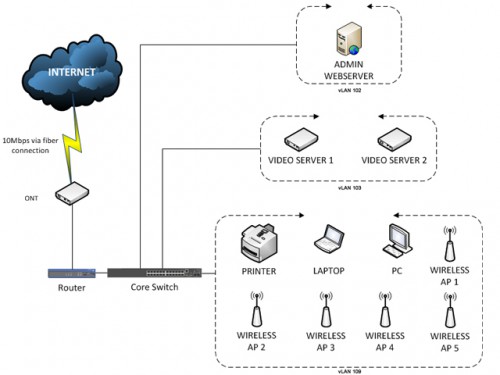
I recently was asked to re-look at the Internet infrastructure of my condo estate and see how we could update it for fibre without too much costs. It was about 11 years old, making use of old 100BaseT equipment and still using an ADSL uplink, a real pain considering  everyone was now on fibre. We had 5 wireless units around the estate, 2 user PCs and a network printer in the management office, a web server and 2 video cam servers to be fed from a single uplink. Now all these devices were already on their own internal vLANs on the old setup which I had put in place some time ago and there was absolutely nothing wrong with the internal setup. All we wanted at this point was to swap the ADSL uplink for a fibre uplink. The issue was that everything was configured through an extremely outdated 3Com core switch and with the new fibre setup, there was no replacement for this, neither was there any technical assistance rendered – all part of keeping things on the cheap (including asking me to design and set things up for free). Basically I wanted this:

dpnet2

Now the ONT and router were provided of course by the ISP, but we had no core switch, neither did we want to spend a couple of thousand on one. So the dilemma was how to get the functionality of a high end switch without spending that kind of money? Answer – don’t. Get a SOHO Layer 3 switch (your typical home cable router) which can be run with some of the more awesome 3rd party firmware like DD-WRT or OpenWRT and get all the functionality you need at a fraction of the price. The functionality I needed was pretty basic, One-To-One Network Address Translation (NAT), Virtual LAN (vLAN) support (didn’t need tagging) and a DHCP server. Now I had a bevy of choices, Tomato, DD-WRT or OpenWRT to name a few and I went with OpenWRT. I’m not a fan of Tomato’s UI and neither was I fond of the haughty attitudes of the DD-WRT developers and also since I had been a user of OpenWRT from it early implementations, I decided to stick with it.

So just a little education first – what exactly was the functionality I mentioned? I’m sure you’re all familiar enough with a DHCP server, thats what dishes out IP addresses automatically to the clients that connect to the network. What about One-To-One NAT and vLAN support and what is tagging (even though it wasn’t needed)?

Firstly, One-To-One NAT is mapping multiple public IPs to multiple private IPs. The common NAT that most of you folks do at home, is to map your public IP address and a port number to a private IP address and a port number. The reason you use port numbers is because you only have 1 public IP address and using different ports are a good way to share that 1 public IP with a host of services you want to run (which obviously run on different ports). When you have a couple of public IPs, you can afford to map the entire public IP to an entire private IP including all its ports. So for example, If I had public IP addresses, eg: 136.130.20.11 – 136.130.20.15 (5 public IPs) I could map each one of those addresses to machines on my private IP range:

136.130.20.11 -> 172.28.1.11
136.130.20.12 -> 172.28.2.12
136.130.20.13 -> 172.28.3.13
136.130.20.14 -> 172.28.9.14
136.130.20.15 -> 172.28.9.15

And when I access the public IP, say 136.130.20.12, it would route all traffic to my machine on my private network with the private IP, in this case, 172.28.2.12.

Now onto vLANs. The vLAN is a virtual LAN. It is a means of segregating a network into distinct network groups, separate of each other without using a physical switch/router. So with 1 switch, you could create a few vLANs and depending on how you configure things, they may or may not be able to see each other and pass data between each other.

If its tagged, it means all data passing through will be tagged with the vLAN’s id. Tagging is primarily used to pass vLAN data across different network devices in more complexed network setups, where, the (for example) the Human Resource vLAN may span different floors and offices and data would have to pass through several edge switches through which data from other vLANs also pass through. The tagging is a means of identifying the data so that it knows how to pass from switch to switch such that (for example) all the machines in the Human Resource vLAN can see and talk to each other.

Again as with my hotspot posts, I’m not going to detail installing OpenWRT, there are tonnes of guides out there and its really not rocket science.

Setting Up vLANs

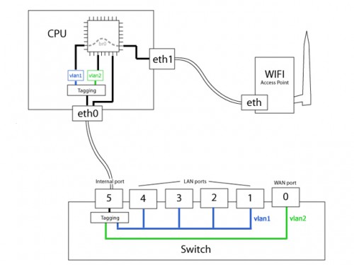
Now there is already a vLAN setup going with the router, the hardware basically creates 2 vLANs, vLAN 1 for your internal LAN data and vLAN 2 for your WAN data (as far as OpenWRT is concerned anyway). These vLANs are tagged so the processor knows which packets belong to which network (LAN or WAN) and hence how to pass the data. Typically for a 4 port router its this:

openwrt-switch-logical

What we are going to be doing is essentially adding to these vLANs. Also instead of having all (usually) 4 of your LAN ports on vLAN 1, we isolate the ports for different vLANs. So for example, I could have one vLAN for staff machines on port 1 (via a switch), another vLAN for video cameras on ports 2 and 3 and a third vLAN for wireless APs on port 4.

Open up your OpenWRT web UI, click on the ‘Network’ tab, then select the ‘Switch’ tab. You’ll see a graphic representation of the ports on your router. Don’t worry if you see more ports than your router actually has, some versions of OpenWRT don’t pick up the right number of ports. ‘Port 0’ is your WAN Port and ‘Port 1’ is the first of your LAN ports – work your way up from 1 with the number of ports your router has. The last port (CPU Port) is an internal port (not visible on the router) that links back to the processor. As shown in the figure above, its labelled as Port 5. If you had 8 LAN ports it would be Port 9 and so on. For any of the vLANs, this CPU port must be set as ‘tagged’ so the data is embedded with the vLAN id and hence the processor knows which vLAN the data passing through these ports belongs to.

For this post, the router in question is a 4 port router, so the LAN ports we will be looking at are ‘Port 1’ to ‘Port 4’.

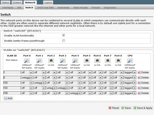
You will notice at the start, under vLAN 1, ‘Port 1’ to ‘Port 4’ are all set as ‘untagged’, meaning they belong to the same vLAN and that data is not being tagged as it passes through them. We are going to:

– create 3 new vLANs (vLAN 102, vLAN 103 and vLAN 109)
– assign ‘Port 1’ to vLAN 102
– assign ‘Port 2’ and ‘Port 3’ to vLAN 103
– assign ‘Port 4’ to vLAN 109
– deassign all the LAN ports from vLAN 1

Operationally, this means:

– Click the ‘Add’ button and create 3 new vLANs vLAN 102, vLAN 103 and vLAN 109
– Under vLAN102 set ‘Port 1’ to ‘untagged’
– Under vLAN103 set ‘Port 2’ and ‘Port 3’ to ‘untagged’
– Under vLAN109 set ‘Port 4’ to ‘untagged’
– Change all the ‘untagged’ to ‘off’ for vLAN 1

‘Port 0’ will remain as ‘untagged’ on vLAN 2.

openwrt-switch1

So looking at the above, you can see that I am actually keeping vLAN 1, but not assigning any ports to it. Fact is, the router’s LAN IP (typically 192.168.0.1 or 192.168.1.1, but in my estate’s setup 172.28.1.1) is on vLAN1 and, if you’re using a wireless router (which you most likely are), the wireless DHCP range will be on vLAN 1, so you should NOT reassign or delete vLAN1. In other words, even though there are no ports assigned to it, the router itself is still making use of vLAN 1.

Once you click ‘Save & Apply’ and if you are on a wire connected to any of the LAN ports, you’ll find yourself kicked off the network and without an IP address (we took all the ports of vLAN 1 remember?) The router’s DHCP service is only configured by default for vLAN 1. No ports assigned, means no IPs dished out. If you’re connected to the router via the wireless, then you’re ok (wireless is on vLAN 1 so you’ll still get an IP if you’re on wireless). For this reason, I suggest you configure the vLANs one by one, setting each one up individually then repeating the process for the remaining vLANs that you want setup, or at least leaving ONE port still on vLAN 1 for you to remain connected.

Assuming you’re still connected after the ‘Save & Apply’, if you go to the OpenWRT web UI, click on the ‘Network’ tab, then select the ‘Interface’ tab, you’ll see the virtual interfaces for each of the vLANs you created, on top of the default virtual interfaces for vLAN 1 (labled ‘LAN’) and vLAN 2 (labled ‘WAN’).

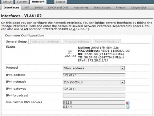
Now to configure the network, subnet, DHCP for the individual vLANs created.  Firstly click on the ‘Edit’ button under the ‘Actions’ column of the vLAN to be configured. Now since each interface is going to act as the gateway for the vLAN, choose ‘Static address’ as the ‘Protocol’. Fill up the IPv4 information (IP, netmask) – this can be any network class and subnet segregation (I’m using a whole class B network with 256 IPs). Then select the gateway address, which will be the LAN address of the router, (in this case  172.28.1.1). To understand why this is so, you have to understand that your router is ultimately the one thats processing all the data and telling it how to go out to the internet/intranet and come back with whatever you want. So each vLAN interface will have to pass its data through the actual router (hence why you use its IP as your gateway).

After everything is configured for that particular vLAN, you’ll have something like this:

openwrt-iface2

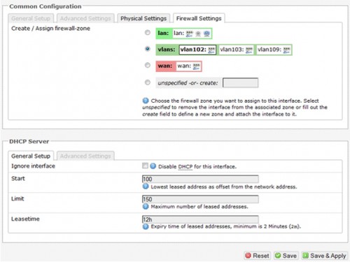
Next go to the ‘Firewall Settings’ tab and make sure the firewall zone is set for the vLANs as below.

openwrt-iface1-fw

This implies that all the vLANs will be able to see each other and communicate with each other. If you want complete vLAN isolation (where the vLANs have absolutely no communication between them), it can be set up under the custom firewall rules later.

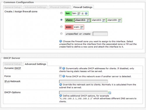
Next we set up the DHCP service for the vLAN. Under the ‘DHCP Server’, ‘General Setup’ tab, make sure ‘Ignore interface’ is not checked. Set the starting IP and the number of IPs and the leastime for the IP (accept the defaults unless you have some special requirements). Under the ‘Advanced Settings’ tab, ensure ‘Dynamic DHCP’ is checked, then click on ‘Save & Apply’.

owrt-dhcpadv

Now repeat the above for remaining vLANs created, using different IP ranges (for the case of my estate setup, 172.28.3.1/24 for vLAN 103 and 172.28.9.1/24 for vLAN 109).

This last step is optional. I did mention about adding vLAN isolation via the custom firewall rules. You can do this by going to the ‘Firewall’ tab and selecting ‘Custom Rules’, then add the following into the text area and click ‘Submit’:

iptables -I FORWARD -i vlan+ -o vlan+ -j DROP
iptables -I FORWARD -i vlan+ -o vlan1 -j ACCEPT
iptables -I FORWARD -i vlan1 -o vlan+ -j ACCEPT

This basically tells the firewall to drop any packets from any of the created vLANs that are trying to reach each other (first line) effectively killing all communications between the vLANs and achieving vLAN isolation. It then tells the firewall to allow any packets from the other vLANs to vLAN 1 (second line) or from vLAN1 (third line) to any of the other vLANs. This is to ensure data can go out from the router and come back in – remember, the router is the gateway for all the vLANs.
And thats that for the vLAN setup. If everything was done properly, you can plug in your laptop with the wire to each of the ports and see that it gets IP addresses on the IP ranges you specified. Plug in two machines to check the vLAN isolation – you shouldn’t be able to ping either machine from the other. Lastly check to see that your machines have internet access.

Configuring One-To-One NAT

This is relative simple, considering its all cutting and pasting of network config commands and firewall rules.

To assign an IP address to the WAN interface, you simple issue an ‘ifconfig’ command for that interface.

ifconfig <interface> <IP> <subnet mask> broadcast <broadcast address>

If you look at your ‘Interfaces’ tab under ‘Network’, you can see that your WAN interface is designated ‘eth0.2’. You can actually get this information by issuing the following command at a command line for the router (if you’ve enabled SSH – Google it if you don’t know how to):

/sbin/uci -p/var/state get network.wan.ifname

That will also return you ‘eth0.2’. So to assign an IP address of say 136.130.20.11 (for example with netmask 255.255.255.0, broadcast 136.130.20.0) to the WAN interface do:

ifconfig eth0.2 136.130.20.11 255.255.255.0 broadcast 136.1130.20.0

If you have multiple IPs to assign to the WAN interface you do:

ifconfig eth0.2:1 136.130.20.11 255.255.255.0 broadcast 136.130.20.0
ifconfig eth0.2:2 136.130.20.12 255.255.255.0 broadcast 136.130.20.0
ifconfig eth0.2:3 136.130.20.13 255.255.255.0 broadcast 136.130.20.0
ifconfig eth0.2:4 136.130.20.14 255.255.255.0 broadcast 136.130.20.0
ifconfig eth0.2:5 136.130.20.15 255.255.255.0 broadcast 136.130.20.0

This is called ‘plumbing the interface’ (like branching pipes from a main pipe, hence the ‘plumb’ reference). You can put this into a shell script format and add it to the router’s local start up section so that it runs at every boot. Click on ‘System’ and select the ‘Startup’ tab and scroll to the ‘Local Startup’ section at the bottom and add the following into the text area and click ‘Submit’:

IFNUM=0
STARTOCT=11
ENDOCT=15
WANSFX="136.130.20"
NETMSK="255.255.255.0"
BRDCST="136.130.20.0"
WANIF=`/sbin/uci -p/var/state get network.wan.ifname`

for i in `seq $STARTOCT $ENDOCT`
do
  IFNUM=`expr $IFNUM + 1`
  ifconfig $WANIF:$IFNUM $WANSFX.$i $NETMSK broadcast $BRDCST
done

This auto detects the WAN interface name (might not always be ‘eth0.2’) and loops through the last octect of the IPs, plumbing the interface with the IPs.

So now your WAN interface will accept all traffic for any of the above addresses. The next part will be to configure the firewall rules to forward the data for the IPs to the right private IPs. Nothing more than adding stuff to the ‘Custom Rules’ under the ‘Firewall’ section again. Copy the following code and alter the WAN IPs and LAN IPs (which the WAN IPs are supposed to point to) for every public to private NAT you have:

iptables -t nat -I PREROUTING -d <PUBLIC-IP> -j DNAT --to <PRIVATE-IP>
iptables -t nat -I POSTROUTING -s <PRIVATE IP> -j SNAT --to <PUBLIC-IP>
iptables -I FORWARD -d <PRIVATE-IP> -j ACCEPT

This basically routes all packets from the public IP to the private IP (first line) and all packets from the private IP to the public IP (second line) and forwards all TCP/UDP packates for all port numbers of the public IP to the same port number on the private IP (third line). This is kind of a “allow all through” situation. If you want only forward certain ports, then specify the ports to allow. For example, to allow SSH and HTTP traffic, forward only packes for ports 22 and 80:

iptables -I FORWARD -d <PRIVATE-IP> -p tcp --dport 22 -j ACCEPT
iptables -I FORWARD -d <PRIVATE-IP> -p tcp --dport 80 -j ACCEPT

A complete working example (the one I gave up top about 136.130.20.12 pointing to 172.28.2.12 via NAT) allowing only SSH and HTTP traffic would be:

# WAN 136.130.20.12 -> LAN 172.28.2.12
iptables -t nat -I PREROUTING -d 136.130.20.12 -j DNAT --to 172.28.2.12
iptables -t nat -I POSTROUTING -s 172.28.2.12 -j SNAT --to 136.130.20.12
iptables -I FORWARD -d 172.28.2.12 -p tcp --dport 22 -j ACCEPT
iptables -I FORWARD -d 172.28.2.12 -p tcp --dport 80 -j ACCEPT

Do this for every WAN IP pointing to an private IP and then click ‘Submit’ and after that you should have the translation working fine.

And that folks, is how you do vLANs and One-To-One NAT without spending thousands.

References:
One-To-One NAT
vLAN Detached Networks

April 23, 2014

VPNs


VPN

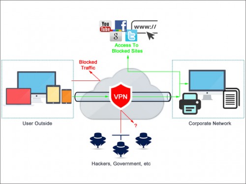
That picture up top (which I created from scratch on my own by the way, with a few influences from other sites), is a typical representation of a Virtual Private Network (VPN). Companies very commonly have a VPN for their company network to make sure some semblance of confidentiality and privacy are maintained. So what is VPN?

Have any of you guys watched the early 70s show Hogan’s Heroes? Its a show about a group of allied soldiers in a German Prisoner of War (POW) camp who are there by choice. They have a massive underground operation to sneak plans in and out of the camp and bring other allied pilots shot down in and out of the camp while arranging for them to be rescued. The leader of the group, Col. Robert E. Hogan, and his band of misfits regularly exit and renter the camp through a series of tunnels which have been built from the outside into the camp, which are so expertly hidden, secured and fortified that only the ones who built them, know anything about them and accessing them.

So now think of your company as the POW camp and you and your other colleagues are Col. Hogan and his team. You guys need to get in and out of the camp so you create tunnels from the outside to the camp. These tunnels bypass any of the fences and walls that keep folks out of the POW camp and keep camp activities from being seen by people on the outside. The tunnels become an extension of the POW camp grounds.

So when you create a VPN connection to your company, what you’re essentially doing, is creating a secure tunnel that extends the company network to where ever you are. So long as the connection is active, its like you are virtually in the company network, even though you’re no where in the company. You have access to company resources, files, servers, etc which you wouldn’t have access to once you plug your laptop out of the ethernet connection at your office. Most folks think VPNs only protects confidentiality and privacy, but on top of that, there is networking aspect which is often ignored.

Lets touch on that network aspect first. As you may or may not know, the current implementation of IP addresses (aaa.bbb.ccc.ddd), IPv4 is fast running out, so you can’t issue a public IP address to every single network entity you have. You want to save the public IPs for resources that should be accessed by the general public, for example, your website or your public FTP server and use private IP ranges (eg: 192.168.x.x, 172.28.x.x, 10.0.x.x) for all the other devices. In some cases, where one only has a single public IP (there are companies like this, trust me, I know), what is done is to use Network Address Translation (NAT) to map several private IP addresses to that one public IP. This is called One-to-Many NAT.

Having a VPN allows you have private IPs for your company resources that don’t need to be public, but still allow employees outside the company walls (eg: overseas on official visits, on holiday, etc), access to those resources. It also allows for one to bypass firewalls in certain counties – China for example, where access to Google and Google services has been completely cut, companies who have switched their company email to Google Apps email, have no access until they activate their VPN. Doing so, their internet traffic is routed back through their company network and then to Google, rather than through whichever ISP in China they are connected to in which case traffic gets blocked. I recently explained this concept to a friend who was in China and who couldn’t for the life of him get his emails and he very predictably responded “Oh, but I though VPN is for security?” – yes it is for security, but as explained, not only security. Speaking of which, lets get to the security aspect of VPNs.

Looking at most implementations, you’ll find at least two prominent types of VPN connections, PPTP and L2TP/IPSec and folks have been using them for years, blissfully ignorant of just how secure they really are – afterall, if the company swears by it, then it must be good right? Wrong.

Since the Snowden reveal, there’s been a lot said about just how secure security is, especially since government agencies have been chipping away at the integrity of the protocols used for decades allowing them to read in transit what is supposed to be unreadable.

There are several reviews on the types of VPN available these days and just how secure they are (BestVPN has a good article, though there are some inconsistencies, but none the less its a good read). I won’t reiterate whats in the article or dozens of other articles, but the long and short of it is, PPTP and L2TP/IPSec isn’t as secure as its supposed to be.

If you’re going to implement a PPTP solution, then its not for security purposes, but mainly for network access to a private resources. The script on this blog should get one up and running without even needing to understand much, though the explanations are all there if you’re interested:

Jesin’s Blog – Setting up a PPTP VPN Server on Debian/Ubuntu

L2TP/IPSec should only be implemented for non-critical data, data that you want private and folks won’t spend more than 5 minutes trying to decrypt. This is because the IPSec encryption has potentially been compromised by the various governments (curse you governments!).  If you want to set something like this up, download the setup script (for Ubuntu) here:

Setup a simple IPSec/L2TP VPN Server for Ubuntu and Debian

If you want to use L2TP/IPSec, consider using the Internet Key Exchange v2 (IKEv2) IPSec tunneling protocol. Its offers a lot more security than your standard IPSec. Setting this up on Ubuntu is typically a matter of installing StrongSWAN over LibreSWAN (see here).

All things considered (availability of clients, security, etc) your best bet would be to setup an OpenVPN server, which offers extreme security and multiple encryption algorithms. Its basically what most commercial VPN vendors and a lot of companies are switching to these days anyway. The drawback is having to download a 3rd party client and custom built profiles. Setting up the server, isn’t trivial either. Instructions can be found here (pertains to Ubuntu 14.04, but its generic enough for most distros):

How To Set Up an OpenVPN Server on Ubuntu 14.04

Of course you could also spend a couple of thousands and get a commercial, dedicated VPN appliance, but unless you’re running your own business and have lots of corporate secrets worth millions and millions, I don’t figure its a practical idea (if you had millions, you wouldn’t be on my site anyways).

However if you’re a typical home user that just wants simple security of non critical data or basic access to your home network from outside, you now have my take on VPNs. You want to set one up, make sure you know what your needs are. Don’t go tearing your hair out trying to implement OpenVPN or IKEv2 when all you need is access to your home network from outside – PPTP is all you need and you can have that up and running in under 5 minutes. For a security concerns, as long as you don’t intend to go to battle with certain governments, the default L2TP/IPSec implementations are find (also easily setup in under 5 minutes).

As with everything else, know what your goals are before you implement anything.

April 6, 2014

BioSlax Is Dead


bioslax-nomore

Yes – you heard right!

After months and months of testing, contemplating over switching to Porteus and waiting for Tomas to come up with a new version of Slax, I decided it just wasn’t worth doing anymore. I had been trying to use Tomas’ Linux Live Scripts to make a modular Ubuntu, which would at least give us the option of having a software repository with apt-get, but the Linux Live Scripts just didn’t work with Debian (even though Tomas claims they do). The methods of making a live media Ubuntu were all not modular and proceeding with that would actually be a regression, considering we had come from a non-modular live cd to a fully modular Slax. The decisions of the kernal contributors to do away with bootsplash in preference of Frame Buffer also meant very little customizations to the look and feel. Given all that and the effective size and cost of thumbdrives these days which can hold a fully installed Linux, and be booted from almost any modern system, I figured there was no point carrying on with BioSlax.

Its been a great run and I learned a whole lot creating it, (the lessons have been extremely useful in other projects), but for now, BioSlax development is shutdown.

March 28, 2014

WD-EX4


WDEX4-01

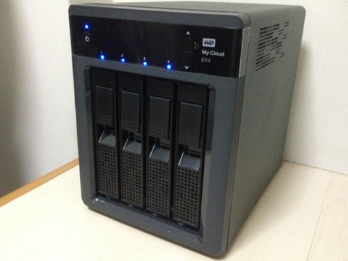
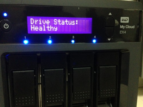
As readers would know from my first few posts, I’ve already got a WD My Book Live Duo DLNA NAS which houses all my HD media and streams it to my home entertainment system. It would appear that my zest for good HD quality movies with excellent sound had almost fully depleted the 6TB (RAID 0) of space on that device. I was looking at about less than 2TB remaining. I would either have to copy the more than 4TB of data out, get larger drives and go through the pain of expanding the size like I did before then copy the data back in, or get a new device. The other consideration was that I had no good recovery plan should the NAS drives fail for any reason. With all that in mind, I decided on getting WD’s EX4 My Cloud DLNA device. A hot-plug 4 bay device with a simple LCD scrollable display and fully redundant power and network (but strangely no redundant cooling fan), it supports RAID 1, 5, 10 and JBOD modes and has two USB 3.0 ports for attaching external storage to it.

WDEX4-01a

The hard drives just slot into the enclosure courtesy of a spring loaded swivel handle, which one has to be very careful with – if you accidentally hit any of the handles, it could pop the disk out while in operation, which would lead to a rebuild that believe me takes longer than you’d have time for (even for a low capacity setup).

WDEX4-02

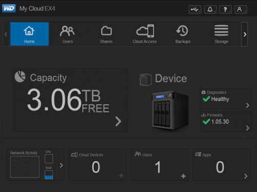
The web interface is pretty intuitive and user friendly, allowing one to configure and operate the device easily. The interesting thing about this device is that it allows for 3rd party application modules to be setup. You can have Joomla!, BitTorrent, Icecast and many other apps running on the device utilizing the storage with a few clicks. It also allows full integration with other cloud vendors like Dropbox and Google Drive and also does the basic backups like TimeMachine for Macs or just simple external storage backups (via the USB 3.0 ports).

WDEX4-03

The other thing I like about it, is the various configurations you assign to your two network interfaces – round robin, active backup (default) or even 802.3ad link aggregation. This means if you have the right switch/router in place (eg the Asus RT66U with custom Merlin firmware, Netgear GS108T Smart Switch), you can actually combine your network ports to double your throughput.
All that doesn’t come cheap however, you’ll be out about S$600 just for the device alone without any drives, but then again, compared to the more prominent brands like QNAP and Synology, this price is pretty good for a system that can do so much.

December 12, 2013

Speed Boost!


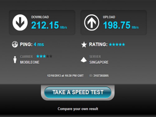
Time files when your internet connection is as fast as what I have. Back at the end of 2011, I jumped onto the fiber broadband-wagon and have been burning rubber every since. M1 started off back then with the 100Mbps package plans as their basic offering, just like all the other ISPs. Difference being, that M1 actually delivered on the speeds. For the last two years that I’ve been on their 100Mbps plan (100Mbps down, 50Mbps up), I’ve been getting consistent average speeds of 105Mbps down and about 85Mbps up – way more than what was promised. Notice I said consistent – not just during “off peak” hours. Where other friends were bitching about Singnet and Starhub, I was blissfully happy with M1.

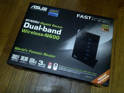
Well, my two year contract with M1 was coming to and end, so I recontracted my plan with them – they don’t offer 100Mbps plans anymore, instead their basic package plan starts off with 200Mbps. At no change in my already very-low-cost monthly subscription, I got a speed boost too with 3 months free subscription (I missed the SITEX promo of 6 months free – bummer!). M1 even threw in a free ASUS RT-N56U wireless N router on top of that.

M1-Asus-RT-N56U

Now the N56U is arguably one of the top five gigabit SOHO routers in the market and its hardly low cost. I already had my TP-Link TL-WR2543ND gigabit router which had been serving me perfectly for the last two years, so my initial plan was to just keep the N56U as a spare or sell it. That was until I found out that my TP-Link was more of a gigabit switch rather than a gigabit router.  All routers have what we call  WAN-to-LAN (WTL) throughput. The value of this figure is basically how much data the router can process passing from the WAN interface to the LAN interface in either direction (up or down). Sadly the WR2543ND’s WTL maxes out at 120Mbps on the default firmware. I tried switching to OpenWRT and DD-WRT where it was said these alternative firmwares could actually push the WTL to about 235Mbps, but it still capped out at 120Mbps. The switch ports (LAN) were all hitting a full 1Gbps though.

The ASUS however, has a WTL of nearly 900Mbps, making it more than capable of handling my 200Mbps bandwidth and with those numbers, this router should last me into my next contract as well (unless they start handing out 1Gbps package plans at low prices by then). With little choice, I unwrapped the ASUS and set it up – the default firmware is an August 2013 build and its absolutely horrid with loads of stuff that makes a good router completely missing, but thankfully the latest October 2013 build fixes that. Interface is sophisticated looking, but its not complicated and has all the bells and whistles that made my WR2543ND great, including the dual band 2.4 and 5.0 GHz wireless bands, media server, FTP server for the 2 USB ports that even support a large list of AIO printers. The only gripe I have with it is that I can’t change the username from ‘admin’ to something else. From a security stand point, it bugs me that I can’t do this, but in an overall sense, its a trivial matter. In any case with ASUS in place, my connection started rocking with the new speeds, and again M1 was giving me way more than what their plan promises – no complaints there!

M1-200Mbps

With that done, I re-used the WR2543ND as a wirless switch (not router) – bypassing the WAN port and only using the LAN ports to extend my wireless signal. All in all, its working out fabulous, so if you’re getting your own router, make sure you know what its WTL is to which SmallNetBuilder has pretty good comparison charts.

Oh and for all of you out there who will be upgrading your fiber connections soon and who are already Red or Green, think Orange this time round.